Controls
STEP Viewer
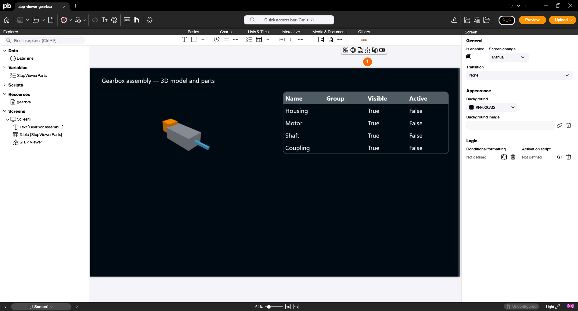
The STEP Viewer Control displays a 3D CAD model directly inside your Peakboard application. It reads the model, breaks it down into its individual parts and can write those parts into a list — so a dashboard can show, hide and highlight single parts through ordinary data bindings, without a single line of script. You can find the STEP Viewer Control in the Peakboard Designer within the Others group (1). Drag and drop the icon into your designer or double-click it to place it on your workspace.
Configuration and Properties
1 Loading a model
Double-click the control to open the resource selection and pick the model file. The file is packaged into the .pbmx file as a resource, exactly like an image, so the project stays self-contained.
Two formats are supported:
- STEP (
.step,.stp) – the ISO 10303 exchange format that virtually every CAD system can export. - glTF (
.glb,.gltf) – already tessellated, which means it opens instantly and needs considerably less memory than a STEP file.
If you have the choice, use glTF. A STEP file has to be tessellated when it is loaded, which costs both time and memory — especially on a Peakboard Box.
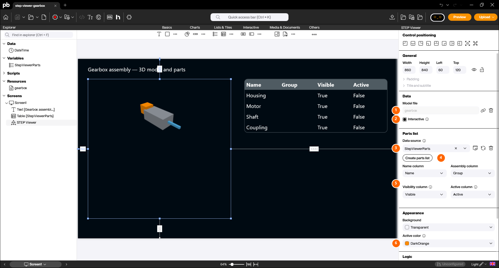
The chosen file is shown under Model file (1). With Interactive (2) you decide how the model behaves: when it is enabled the model can be rotated and zoomed, when it is disabled only a static snapshot is displayed, which saves performance.
2 The parts list
This is what makes the control more than a viewer. The STEP Viewer can fill a list with one row per part of the model — and it reads changes to that list back, so writing into the list changes the model.
- Select the list that should receive the parts under Data source (3). Any list of the project can be used.
- The Create parts list button (4) does the work for you: it creates a matching list named
StepViewerParts, binds it and fills in the column mapping. This is the fastest way to get started. - Below that you map the four columns (5):
- Name column – receives the name of the part.
- Assembly column – receives the sub-assembly a part belongs to.
- Visibility column – a boolean column. Clearing it hides the part in the model.
- Active column – a boolean column. Setting it highlights the part in the active color. Only one part can be active at a time.
Because the visibility and active columns are written back to the model, you can bind them to a Table, a Checkbox or a data source and control the model entirely through data.
3 Appearance
Under Appearance you define the Background of the control and the Active color (6) — the color a part is painted in while it is marked as active. Leaving the active color empty disables the highlight completely. The default is DarkOrange.
Scripting
Give the control a name under “Used in scripts” to address it in a script. The script surface is deliberately small, because showing, hiding and highlighting parts is done through the bound list and not through methods:
ModelSource– the file name of the model to display, e.g."chassis.glb". Only files that are packaged into the project can be selected, exactly like with the Image Control.ActiveColor– the highlight color of the active part.
-- swap the displayed model at runtime
StepViewer.ModelSource = "chassis.glb"
The result
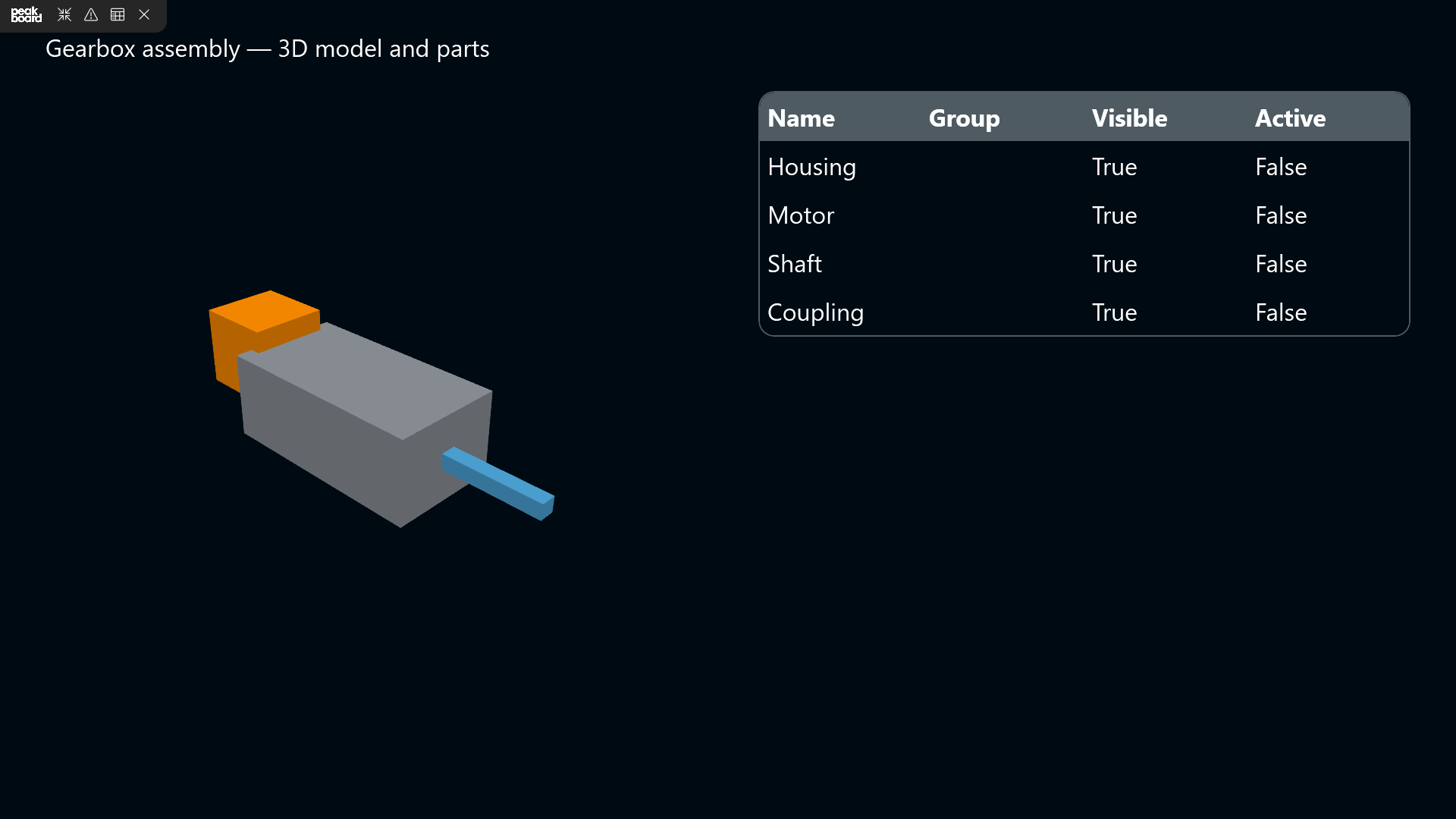
In the preview and on the Peakboard Box the model is rendered next to its parts list. Note that the model does not appear instantly: the 3D libraries and the model itself are loaded asynchronously, and a large STEP file in particular can take a moment before the first frame is drawn.
Example project
You can download the finished example and open it in the Peakboard Designer to explore the model resource, the automatically created parts list and the Table binding: Gearbox assembly (.pbmx).